






It is very important to understand the color coding in a three-phase electrical system to be able to ensure safety, efficiency, and compliance with industry standards. If you are the electrician, engineer, or facility manager, then it is very necessary to understand the significance of wire colors and their corresponding voltages to avoid costly mistakes and hazards. This guide will look into the three-phase color codes that are standard all over the world, explain the role of the colors in determining the phases and voltages, and highlight their importance in system integrity maintenance. You will be able to see how these codes make the complex electrical setups easier and, at the same time, promote safer and more efficient operations once you have come to the end of this guide.
Introduction to 3 Phase Color Code
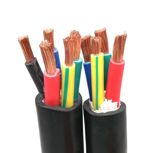
The three-phase color code is a universally accepted method that is utilized for the identification of the phases and voltages in the wiring of three-phase power systems. This color scheme guarantees the right connections and makes maintenance easier in different installations. Although the exact codes may differ by region, the most general standards are as follows:
- In the United States (according to NEC): Black, red, and blue are used for phases in 120/208V systems; brown, orange, and yellow for 277/480V systems.
- In Europe (IEC Standard): Brown, black, and grey for phases.
- In the United Kingdom (Post-2004): Brown, black, and grey, which are in line with the IEC standards as a result of harmonization.
These codes are vital for the elimination of wiring mistakes, the minimization of system failures, and the establishment of uniform safety measures in the installation of electrical equipment of different types.
What is a 3 Phase System?
A 3-phase system is an electrical power distribution technique that employs three alternating currents (AC) with the same frequency and amplitude but staggered by 120 degrees between them in time. The three-phase system is one of the most efficient methods of power distribution, hence its ubiquity in industrial, commercial, and large residential areas. Besides, it gives the advantage of less conductor material requirements and even reduces transformer and switchgear costs.
In contrast to single-phase systems, which produce power that is fed in an alternating manner from zero to maximum, the three-phase system guarantees a steady power supply. This is down to the fact that after the three waveforms are displaced from each other by 120 degrees, they all average, then stay positive. The upshot of this is that the powering of motors, machines, and other devices becomes more stable and effective.
There are two basic configurations for 3-phase systems—Delta (Δ) and Wye (Y). The Delta configuration connects all the output ends of the phase windings in series, thus forming a triangle-like structure. High-power transmission systems are the main area where the Delta configuration is applied. However, the Wye configuration connects one end of each phase winding to a common neutral point, thus enabling both single-phase and three-phase loads. The use of this setup is widespread due to its adaptability in terms of voltage levels.
The combination of enhanced reliability, efficiency, and cost-effectiveness is the reason why 3-phase electrical power distribution systems are still the most widely accepted ones worldwide.
Importance of Wire Color Code
The wire color code is a key factor in making the electrical systems safe, efficient, and in compliance with the regulations. The function of each wire in a circuit is identified using standardized color codes that are accepted and used all over the world. This has made the processes of installation, maintenance, and troubleshooting easy and less time-consuming. For example, in the United States, the National Electrical Code (NEC) indicates that black, red, and blue wires are typically used for phase conductors, whereas the white wire is for the neutral conductor, and a green wire or a green wire with a yellow stripe is for the ground.
Moreover, wire color coding is a means of achieving compliance with local and international standards, such as the IEC (International Electrotechnical Commission) guidelines in Europe, where different color codes are applied. For example, in Europe, brown, black, and gray are the colors for the phase wires, the color blue is for neutral, and green-yellow is for grounding. It is very important for companies that operate in multiple countries to comply with these standards, as they help to facilitate the electrical installation and also protect from legal and safety liabilities.
The standardized color coding is beneficial not only to the safety of the electrical system personnel but also to the operational clarity in the complicated industrial settings. The electrical systems at places like data centers, manufacturing plants, and hospitals have to rely on the clear identification of wires to reduce the risk of outages and failures during maintenance.
Overview of Different Voltages in 3 Phase Systems
Three-phase power systems are very common in the industry and business because they are very efficient ways of power delivery. Usually, these systems are designed around particular voltage levels that can be different from one area to another or depend on the application. The following three-phase system voltages are the most frequent ones:
| Voltage Category | Voltage Range | Typical Applications | Characteristics |
|---|---|---|---|
| Low Voltage Systems | 120/208V or 230/400V | Houses and small commercial places | Suitable for lighter loads and balanced power distribution for smaller equipment |
| Medium Voltage Systems | 2.4kV to 35kV | Large manufacturing or big commercial places | Supply electricity over distances up to a few kilometers, usually with transformers |
| High Voltage Systems | 69kV, 115kV, or higher | Power transmission over long distances and heavy industrial use | Large-scale energy distribution networks with reduced power loss over long distances |
The voltage in a three-phase system is decided by the application’s requirements, efficiency, and the standards of the region. For example, North America commonly uses 120/208V and 277/480V systems while European countries prefer 230/400V for low voltage installations. Thus, proper design and compliance with the local electrical code are necessary to provide safety and reliability of the system in different environmental conditions.
Understanding Wire Color Codes
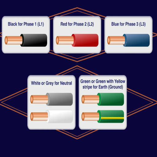
The wire color codes are uniform code systems that aid in recognizing the function of the electrical wires and, thus, the electrical installation can be done safely and efficiently. The particular colors assigned to this purpose are different by area:
North America (NEC Standard):
- Black, Red, Blue: Three-phase systems’ hot/live wires.
- White: Neutral wire.
- Green or Green with Yellow Stripe: Ground wire.
Europe (IEC Standard):
- Brown: Hot/live wire.
- Blue: Neutral wire.
- Green with Yellow Stripe: Ground wire.
Interpreting or applying color codes always requires referring to the local electrical codes because regional differences in regulations or practices may cause variations. Hazards arising from the misinterpretation of color codes include electric shocks and system failures.
IEC Wire Color Code Standards
The standards considering the IEC (International Electrotechnical Commission) wire color code are acknowledged worldwide and created to promise uniformity and safety in electrical installations. A brief overview of the main features is below:
- Live/Hot Wire: Brown
- Neutral Wire: Blue
- Ground/Earth Wire: Green with Yellow Stripe
The said standards are adopted in the countries that are part of the IEC framework, and the aim is to reduce the dangers related to electrical installations and maintenance to the lowest possible level. Nonetheless, it is important to keep in mind that local changes or rules might have a slight impact on the guidelines. For example, some areas may add extra colors or impose special rules for phase conductors in a multi-phase system.
The IEC insists on strict observance of the standards for the safety, reliability, and convenience of identification during electrical works. Misclassification or non-compliance with the guidelines can cause systems to fail or lead to unsafe situations. Electrical personnel and engineers must always refer to the latest IEC documentation and follow the national electrical codes for correct application.
NEC Wire Color Code Standards
The NEC (National Electrical Code) has classified wire color coding as one of the most important practices in the U. S. and also as one of the main steps towards safety. These standards not only help in communication but also in the identification of the wires at the time of installation, maintenance, and diagnosis of problems.
Ground Wires
Ground wires are universally identified by their green insulation or green with yellow bands. Bare (uninsulated) conductors also play the role of grounding wires.
Neutral Wires
Neutral wires are always white or gray. These wires form the electrical loop by carrying the current back to the source.
Phase (Hot) Wires
- Single-Phase Systems: Black and red are often employed for hot wires.
- Three-Phase Systems (120/208/240V): Phase 1 is black, Phase 2 is red, and Phase 3 is blue.
- High-Voltage Systems (277/480V): Phase 1 is brown, Phase 2 is orange, and Phase 3 is yellow.
Special Uses
- Orange wires may also denote live or “always-on” conductors in a few settings.
- Pink or purple wires might point to other controls or sales terminals.
It is necessary to adhere to the NEC wire color code standards not only to ensure functional reliability but also to eliminate safety risks in the electrical installation process. Always verify the color codes in accordance with the NEC and local jurisdictional regulations before proceeding to do electrical work.
Common Color Codes for Phase Wires
Phase wires play a pivotal role in electric systems and are mainly used to transport the load current. The National Electric Code (NEC) has introduced color standards for easy identification as well as safety. A brief comparison of the color code for phase wires in different system layouts is presented below:
| System Type | Phase A | Phase B | Phase C |
|---|---|---|---|
| 120/208V AC Systems (Three-Phase) | Black | Red | Blue |
| 277/480V AC Systems (Three-Phase) | Brown | Orange | Yellow |
| Single-Phase Systems | Black or Red (application determines) | ||
The existing color conventions have become a basis for uniformity in electrical wiring practices and have made it possible to identify the installation and maintenance points easily. Notwithstanding, it is extremely important to check for conformity with NEC standards and also localized electrical codes or regulations for accuracy and safety purposes.
Applications of the 3 Phase Color Code
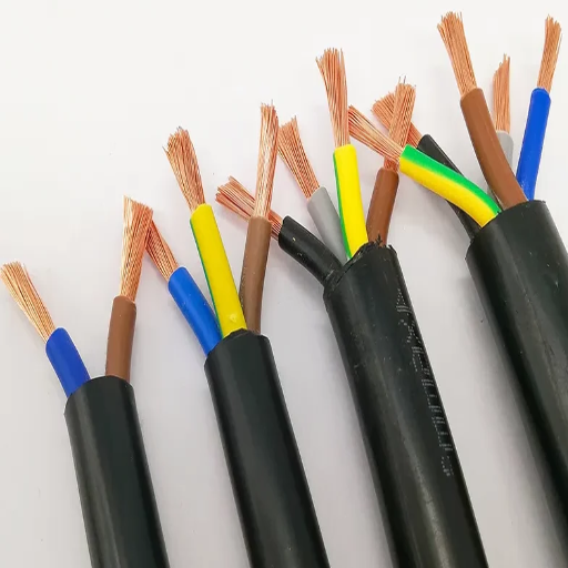
The 3-phase color code is of great importance and is the main reason why electrical systems are safe, efficient, and consistent. It is mainly employed in these application areas:
Industrial Power Systems
The color coding allows the distinct identification of phase conductors in industrial facilities like factories, power plants, and others, thus guaranteeing proper working of heavy machinery plus reducing wiring mistakes.
Commercial Electrical Installations
It finds its place in office buildings, shopping malls, and other commercial areas for the purpose of organizing electrical systems, which subsequently leads to maintenance and troubleshooting becoming easier.
Residential Wiring in Specialized Systems
3-phase wiring with standard color codes, although not typical, can still be found in residential areas where high-demand appliances, for instance, HVAC systems, require a power supply.
Solar and Renewable Energy Systems
The color code plays a vital role in managing power distribution and grid connection of solar farms, wind turbines, and other renewable energy setups; thus, it’s indispensable.
By using these standardized color codes, professionals can be sure of compliance with safety protocols, while at the same time, the risks of operation are minimized.
Wiring in Transformers
Transformer wiring is an integral part of electrical systems and plays a major role in the performance of circuits by taking care of the power transfer in an efficient manner. Proper wiring requires interlinking the primary and secondary windings of the transformer in accordance with the specific voltage and phase configurations. In the case of single-phase transformers, the primary usually connects with the input voltage source, whereas the secondary delivers the desired output voltage. Three-phase transformers, on the other hand, usually choose the common configurations such as delta or wye, which are determined by the network requirements, for their connections.
Color coding in the wiring of transformers is an important part that reduces the chances of mistakenly identifying the connections and minimizes errors in installation or maintenance. The terminals of the primary and secondary sides are marked with standard designations like H1, H2, X1, and X2 to indicate high-voltage (primary) and low-voltage (secondary) sides. Furthermore, grounding is a necessity for safety and to avoid electric shock or damage to equipment.
Transformer wiring has to follow local electrical codes strictly, for example, the National Electrical Code (NEC) in the US, so as to ensure safety as well as operational efficiency. Engineers also have to take into consideration load capacity, impedance, and voltage ratings in order to create and perform maintenance of transformer systems that are reliable. Precise realization increases not only the energy efficiency but also the safety and long-term performance of the electrical system.
Identifying Phase Wires in Electrical Systems
The identification of phase wires is a very important thing that ultimately affects the electrical system setup and its whole functionality. Phase wires, usually color-coded according to specific standards, are the carriers of the live current needed to power the electrical loads. The United States National Electrical Code (NEC) sets the color codes for standard practices, with black, red, and blue wires typically corresponding to the phases of the three-phase system, while the single-phase system usually has black as the color of the live wire. But using color coding to determine wires may be a little tricky if the system is an old one or if it is outside the United States, so in that case, you will have to do a very careful verification during installation or troubleshooting.
The right tools play a vital role in the identification process, such as multimeters that measure voltage levels to confirm the role of every wire. In addition to that, phase sequence testers are used in three-phase systems to check whether the order of the phases is rotating correctly, which is especially critical for the operation of motor-driven equipment. Consulting wiring diagrams and following the local regulations are essential to minimizing mistakes and ensuring safety. Compliance with regulations and the maximum efficiency of the electrical systems are guaranteed if proper procedures are followed.
Safety Considerations in Wiring
When wiring tasks are performed, safety should always be the top priority to avert unwanted situations like electric shock, fire, or damage to the equipment. Before starting any wiring work, always make sure that the power supply has been turned off. It is important to use the proper tools and equipment that have the same voltage and current levels as those involved in the project. Insulation of wires must be done properly, and if there are damaged or worn-out cables, these should be replaced immediately. To keep system stability and minimize electric shock risks, it is a must to follow grounding methods.
Obeying local electrical codes, like the National Electrical Code (NEC) in the USA, is compulsory to prove that the installations are safe according to the established safety standards. Working with live systems necessitates the use of personal protective equipment (PPE), which includes insulated gloves and safety goggles. Furthermore, connections need to be double-checked, and appropriate circuit testers should be used to ensure that systems are functioning properly before energizing. A well-organized workspace and meticulousness cut down the chances of making ordinary mistakes that are nonetheless hazardous in the wiring process.
Different Voltages and Their Color Codes

Wiring in electrical systems is identified by specific color coding according to their voltage levels, which guarantees and contributes to safety in the installation and maintenance process. The most widely accepted standards are as follows:
120/208V (Low Voltage Systems)
| Wire Function | Color Code |
|---|---|
| Live wire for Phase A | Black |
| Live wire for Phase B | Red |
| Live wire for Phase C | Blue |
| Neutral wire | White |
| Earth wire | Green or Green with Yellow Stripe |
277/480V (High Voltage Systems)
| Wire Function | Color Code |
|---|---|
| Live wire for Phase A | Brown |
| Live wire for Phase B | Orange |
| Live wire for Phase C | Yellow |
| Neutral wire | Gray |
| Earth wire | Green or Green with Yellow Stripe |
The aforementioned color codes are in accordance with NEC (National Electrical Code) standards, which are a requirement for safe and reliable electrical installations in the United States. Local regulations should always be checked first for possible additional requirements.
Low Voltage 3 Phase Color Codes
In the case of low voltage systems (i.e., voltages generally below 50V), color codes may differ by application and regional standards. Nonetheless, if we talk about the United States, it is the NEC (National Electrical Code) that sets the following commonly accepted color codes:
Low Voltage Color Standards:
- Blue: Hot wire of Phase A
- Black: Hot wire of Phase B
- White: Neutral wire
- Green or Yellow with Green Stripe: Ground wire
You should be aware that, although these color codes are mainly for low-voltage wiring, certain applications like communication circuits or control wiring might require different color codes. Always verify with local codes or system-specific documentation for compliance and safety. Moreover, any changes or installations must be checked by a licensed electrician.
Medium Voltage Wiring Color Codes
The use of medium voltage wiring color codes is paramount in the safe and accurate recognition of conductors in electric power systems. The codes might be different in different places, but several standards are pretty close to international rules. A general depiction of medium voltage wiring color codes is provided below according to widely accepted practices:
| Conductor Type | Color Code |
|---|---|
| Phase 1 (L1) | Black |
| Phase 2 (L2) | Red |
| Phase 3 (L3) | Blue |
| Neutral | White or Gray |
| Ground | Green or Green with Yellow Stripe |
It is very important to know that medium voltage systems usually have stricter regulations in place because they can cause more damage or injuries. ISO (International Organization for Standardization), NFPA 70 (National Electric Code or NEC), and IEC (International Electrotechnical Commission) standards should always be consulted for requirements that are specific to the application. Besides, some industrial or regional systems might have their own specific variations.
Wiring diagrams and system labels should always be checked against the governing standards, and proper testing should be done before energizing the system. Using certified electricians and following these codes not only ensures operational effectiveness but also the safety and durability of the electrical infrastructure.
High Voltage 3 Phase Wire Color Codes
High-voltage 3-phase wire color codes are mainly regulated by international and regional norms in order to guarantee the safety and uniformity of operations in electrical and industrial systems. The standards that are typically used the most correspond to the ones set by the International Electrotechnical Commission (IEC), the National Electrical Code (NEC), and respective regional regulations such as the British Standard (BS7671).
IEC Standard Color Coding
According to the standard set by the IEC, the color coding for 3-phase systems generally employs the following scheme for phase conductors:
- Brown for Phase L1
- Black for Phase L2
- Gray for Phase L3
- The neutral is light blue, while the protective earth (PE) wire is marked with a green-yellow stripe.
NEC Standard for 277/480V Systems
For non-grounded phase conductors in 277/480V systems, the colors of A, B, and C phases are often indicated as follows:
- Brown for Phase A
- Orange for Phase B
- Yellow for Phase C
- While neutral is gray, the grounding conductor stays either green or green-yellow striped.
It is crucial to always check and confirm the specific color codes when working on high-voltage 3-phase systems by referring to onsite markings, updated wiring diagrams, and current code compliance in the installation region. Accurate identification minimizes miswiring risks and increases system reliability.
Practical Considerations for Wiring
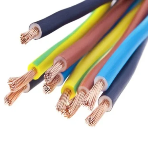
The primary concern when planning and executing wiring installations should always be safety and adherence to regulatory standards, as these are the key factors to ensure system reliability and to effectively reduce risks. The first step in this process should be verifying that the entire system’s components and materials are able to safely handle the voltage and current, as well as the environmental conditions of that specific application. Use certified wires and connectors of high quality that comply with the necessary specifications. Make sure all circuits and connections are clearly labelled to help with future maintenance and troubleshooting tasks. Proper grounding is essential to prevent the equipment and personnel from being affected by electrical faults. Installed wiring should be inspected regularly to check for wear, damage, or corrosion, and any problems found should be dealt with immediately. Always adhere to the manufacturer’s guidelines and check the relevant electrical codes for the area to ensure compliance and safe operation.
Choosing the Right Wire for Your System
The choice of wire for your system must be made after considering a number of factors that guarantee safety, efficiency, and compliance with regulatory standards. The first thing you need to do is to determine the wire size according to the current load of your system, since wires that are too small can get hot and create a fire risk. To find the right wire size for the corresponding amperage accurately, refer to an American Wire Gauge (AWG) chart.
Next, identify the insulation type that will be required by the environment where the wire will be installed. For example, THHN or THWN wires can be used indoors and outdoors, and can withstand high temperatures, while UF and direct burial cables are the best for underground installations. Make sure that the insulation material is suitable for the expected conditions, such as moisture, chemicals, or sunlight.
Finally, check the wire’s voltage rating to confirm that it can cope with the system’s electrical load and still maintain performance. Always opt for wires that are tested and approved by recognized safety standards, like UL (Underwriters Laboratories), to ensure dependability. Considering these factors and following local electrical codes will allow you to set up a safe and efficient electrical system.
Common Mistakes to Avoid
Using Incorrect Wire Sizes
Choosing wires with too low a gauge can lead to overheating and great fire risks. It is necessary to select the wire size according to the load it will be carrying, as electric codes and standards specify.
Skipping Grounding Practices
Not properly grounding the electrical systems may not only cause shock but also that the system. One of the main safety measures is circuit grounding.
Improper Connections and Splices
Poorly done wire connections or using non-approved connectors can create bad contacts, overheating, and then the system fails. Always using proper wire nuts or terminal connections is the best practice.
Overloading Circuits
Plugging in too many devices or going over the circuit’s rated amperage can result in tripped breakers, overheated wires, or failed components. Load calculations should be done right from the beginning during the design phase.
Ignoring Environmental Conditions
The use of non-weatherproof wiring or the failure to protect installations from moisture, sunlight, or extreme temperatures can cause deterioration and shorten the system’s life. Use materials that are rated for the specific environment.
These common mistakes, when avoided, will ensure the electrical system’s life, efficiency, and safety are assured while both local and international standards are followed.
Reference Sources
“Energy-Based Visualization of 2D Flow Fields”
“Ant Colony Optimization for Resistor Color Code Detection”
Frequently Asked Questions (FAQs)
What is the 3-phase color code for electrical wiring?
The identification of the wires in a three-phase electrical system is signified by the 3-phase color code, a standard scheme. In the United States, black, red, and blue are the colors applied for the three phases at 480V, while the neutral is usually white or gray. This, however, may vary in different countries, and some countries follow the color codes by the IEC standard.
How does the wire color code differ for single-phase and three-phase systems?
The single-phase system usually has black as the live wire and white or gray as the neutral. On the other hand, a three-phase system will have three separate wires, generally colored black, red, and blue for the phases. The distinction is very helpful in building wiring and also guarantees proper connections and safety in electrical installations.
What are the common voltages associated with the 3-phase color code?
The common voltages that visibility of the 3-phase color code includes 208V, 240V, and 480V. Each voltage may be associated with a specific wire color code and configuration, which is determined by the electrical system’s design and application, e.g., for motors or pumps.
What is the significance of the phase to neutral voltage in 3-phase systems?
The phase-to-neutral voltage is one of the most important aspects in revealing the connection between the electrical loads in a 3-phase system. For instance, in a 480V system, one would normally have 277V as the phase-to-neutral voltage. This voltage is very important when determining the wiring of the equipment, especially in branch circuits for lighting and other applications.
How does the high-leg color code work in 3-phase systems?
The high-leg color code is one of the things in the 3-phase configurations that is applied in certain ways, and it is mostly practiced in North America. In this configuration, one phase is marked as the high leg, and that is the one that is usually colored orange. This phase provides a higher voltage (usually 240V to neutral) and is generally found in systems that need one 120V and one 240V circuit.
Are there differences in color codes for 3-phase systems across continents?
Indeed, the 3-phase color codes might vary from country to country and continent to continent. For example, in North America, the standard differs from that in Europe or Asia according to the IEC guideline. It is necessary for electricians to know the local standards in order to ensure compliance and safety during electrical installations.
What role does the NEC play in 3-phase wiring color codes?
The National Electrical Code (NEC) sets out guidelines and regulations for electrical installations in the U. S., among which are wiring color codes. By following NEC standards, it guarantees that 3-phase systems are installed properly and safely, thereby decreasing the chance of electrical hazards.
Can I use a cord with the incorrect wire color code for a 3-phase system?
It is strongly discouraged to use a cord that has an incorrect wire color code for a 3-phase system. It may cause confusion, accidents, and wrong connections. Always confirm that the wire color is in accordance with the designated color code for the particular voltage and phase configuration of your electrical system.